Implementing an Autowah Effect in Python using PyAudio

Recently I started playing bass guitar and working some music after a long period of not working on music too much. I was listening to Them Changes by Thundercat and became somewhat curious about the “wah”/envelope follower effect that he uses heavily throughout the song. This effect is pretty standard in funk, and other genres. However, I became interested in how the effect is implemented and decided to throw together an audio development environment in Python and implement this for myself. I used Python, PyAudio, NumPy and SciPy.
Go to github to see the code.
What is an “autowah” or “envelope filter” effect?
So let’s start off with figuring out what we are trying to do. An “autowah” or “envelope filter” effect is one which uses the amplitude of an audio signal to change the filter frequency cutoff of a high-Q (resonating) low-pass filter. The idea is that this is the same effect that a pedal based wah-wah pedal would create, but the modulation of the pedal is done automatically based on how the dynamics of your playing, and a set of control variables. The effect is heavily used in funk music, and pedals that you can buy on the market have names like “dynamic wah”, macrodose, moogerfooger, supah funky, and disco terrapin. Before we go any further, let’s listen to an example of the simple MXR bass envelope filter, and get an idea of what that description sounds like:
So as the filter cutoff moves you get an almost vocal like effect of making a “wow” noise. This is actually quite similar to what happens as you change the shape of your mouth, you are actively changing the filter (your mouth) to accentuate different parts of the sound. You also change the phase relationships of the different tones, which can give the envelope filter a phaser like effect as well.
So with that out of the way, let’s get to a quick example, and onward to the implementation details
The Results
All of the examples will use this little bass riff that I recorded for this demo:
Already you can see all of the controls and settings, the input and output audio and the envelope filter itself, but no effects are being applied. So for a little motivation, here is a setup with a high-Q filter. This means it will have a very aggressive wah effect:
So how do we actually make this work?
Block Diagram
The basic diagram is shown below:
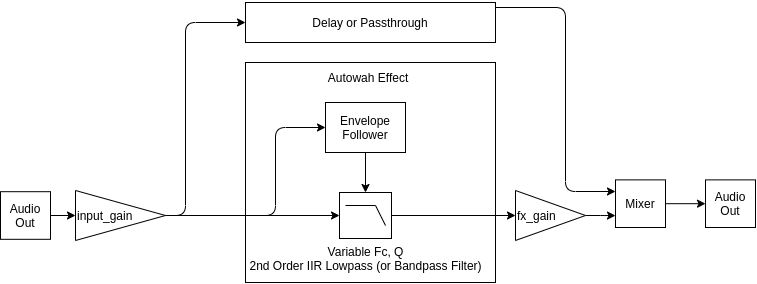
The key components are:
- an envelope filter: which is responsible for taking the input audio and following the envelope (essentially the amplitudes) of the input audio, which is inherently sinusoidal. We will use this to modulate the filter cutoff in the low-pass filter.
- a variable cutoff frequency (Fc) filter: which will filter the input signal. This also should have a tuneable resonance, so we will need to use at least a 2nd order filter. In this case we will use a second order filter with a biquad filter topology. This is what will create the wah sound.
And at present we can control the following things:
| Control Variable | Code Representation | Purpose |
|---|---|---|
| Q | Q | Controls the amount of resonance at the filter cutoff frequency. For no resonance a value <.707 will produce a smooth roll-off. You will still get some effects since the phasing will still be modified, and the cutoff frequency will reduce the gain of some notes being played. When Q is high then the quacking, autowah effect becomes more intense. |
| Sensitivity | sensitivity | The is essentially a gain on the envelope follower, but given how loud you are playing this scales how far between the min and max frequency you can go |
| Min Frequency | start_freq | Sets the lower bound of the cutoff frequencies. |
| Max Frequency | stop_freq | Sets the upper bound of the cutoff frequencies. |
| Filter Type | is_bandpass | Use a low-pass or a band-pass filter. A low-pass filter will allow all of the sound through below the filter cutoff, but a band-pass filter will pass a narrow band round the current filter cutoff. This creates a more extreme effect, but a quieter one. |
| Mix | mix | A value between 0 and 1 where 0 is the input audio, and 1 is full effects. .5 would be a mix of half effects and half input audio |
| Fx Gain | fx_gain | Gain for the effect this is applied before the mixer so the effect can be tuned independent of input gain and mix |
| Input gain | input_gain | How much gain to apply to the input signal before being processed. |
The Envelope Follower
Envelope Follower takes the input signal and creates a signal that traces the amplitudes of the input signal. This article from dsprelated has a pretty good overview of different algorithms. However, many of these are built around decoding RF radio signals where one frequency is being tracks, but we are interested in decoding the envelope of audio signals from 50Hz-1kHz or so (I am playing bass after all). In this case I decided to use a very simple algorithm which will work with variable frequency signals. This takes an absolute value of the signal, then filters that signal with a low pass filter (a 3rd order Butterworth filter).
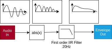
This filter performs well, but at low frequencies the envelope will start to wobble at 2x the fundamental frequency of the audio signal. To fight this a lower cutoff frequency was used of 20-30Hz; however, this means that the filter is not as responsive to sharp edges and sharp decays as it could be. Some form of attack detection, a variable frequency filter, or compression may help improve the response time. I was happy with the response of this Envelope Follower, and I actually like the warble in the filter frequency that is caused by very low notes near the cutoff frequency of the envelope follower. The python for this is fairly simple:
from scipy import signal

class EnvelopeFollower:
    """ """

    def __init__(self, bandwidth_Hz: float = 10, sample_rate_Hz: float = 44100):
        """
        :param bandwidth_Hz: Cutoff frequency to use in the lowpass filter stage
        :param sample_rate_Hz: Sample rate/frequency in Hz
        """

        # Create a lowpass filter with a 2nd order butterworth characteristic
        self._b, self._a = signal.butter(3, bandwidth_Hz, fs=sample_rate_Hz)

        # To use with pyaudio we need to retain the 32 bit float type to prevent unnecessary conversions
        self._b = self._b.astype(np.float32)
        self._a = self._a.astype(np.float32)

        # Store these parameters for getters later
        self._sample_rate_Hz = sample_rate_Hz
        self._bandwidth_Hz = bandwidth_Hz

        # Setup and then initialize the state vector
        self._z = None
        self._is_init = False
        self.reset()

    def reset(self):
        """
        Reset the filter state
        """
        self._z = signal.lfilter_zi(self._b, self._a).astype(np.float32)
        self._is_init = False

    def run(self, x):
        """
        Apply the envelope follower algorithm by taking an absolute filter then filtering the result.

        See: https://www.dsprelated.com/showarticle/938.php
        """
        if not self._is_init:
            self._is_init = True
            self._z = self._z * x[0]

        # Step 1: take the absolute value of the input signal
        abs_x = np.abs(x)

        # Step 2: apply a low pass filter to find the envelope of the signal
        y, self._z = signal.lfilter(self._b, self._a, abs_x, zi=self._z)
        return y

    @property
    def sample_rate_Hz(self):
        return self._sample_rate_Hz

    @property
    def bandwidth_Hz(self):
        return self._bandwidth_Hz
The main complication being around maintaining the filter states self._z between each chunk that is being processed. If you don’t maintain this state then the filter will reset for every chunk of audio that is being processed and cause discontinuities.
The Variable Parameter Filter Design
For a flexible, tuneable variable parameter filter I considered and implemented two options:
FIR Filter with tuneable co-efficients, which I implemented as variable_cutoff_filter and implements this paper: Petri Jarske, Yrjö Neuvo, Sanjit K. Mitra, A simple approach to the design of linear phase fir digital filters with variable characteristics.
An IIR Biquad filter where the state is maintained and the gains are recalculated every time step.
In this case the FIR filter has an issue of needing to recompute all of the coefficients for each sample, while the method used has a low computational complexity, this was still slow and it also meant that the most efficient implementation of an FIR filter was not available. This limited the filter length that was useable. Another downside is the initial filter shape used had a sharp roll-off with no resonance. While the filter can be shaped to add some amplification at the cutoff frequency doing this with variable Q would become more difficult.
The IIR Biquad filter is a 2nd order filter and can be tuned to be a low-pass, high-pass, or band-pass filter, all on the fly if you recompute the gains. The other advantage is that there are 5 total gains to recompute, even though the computational complexity of these gain calculations is higher than in the FIR filter case. Also due to the 2nd order characteristic the resonance can be trivially set with the Q, and due to the infinite impulse response (which include feedback and memory from the output), resonance is a native concept for the filter. So what do different Qs look like:

So as a function of the amplitude of the output of the Envelope Follower we will modulate where the cutoff frequency is, this will basically reduce the volume of anything past the cutoff frequency (as well as effect the phase relationships). In addition to this the region around the cutoff frequency will actually be amplified as a function of the volume of the input signal.
Implementation
import numpy as np
import numba


@numba.jit()
def _calculate_lowpass_gains(wc, Q):
    K = np.tan(np.pi * (wc))
    norm = 1 / (1 + K / Q + K * K)
    b0 = K * K * norm
    b1 = 2 * b0
    b2 = b0
    a1 = 2 * (K * K - 1) * norm
    a2 = (1 - K / Q + K * K) * norm
    return (b0, b1, b2, a1, a2)


@numba.jit()
def _calculate_bandpass_gains(wc, Q):
    K = np.tan(np.pi * (wc))
    norm = 1 / (1 + K / Q + K * K)
    b0 = K / Q * norm
    b1 = 0
    b2 = -b0
    a1 = 2 * (K * K - 1) * norm
    a2 = (1 - K / Q + K * K) * norm
    return (b0, b1, b2, a1, a2)


class VariableCutoffBiquadFilter:
    """
    Biquad Filter Implementation with Variable gain parameters. This assumes a LPF


    References:
        - [1]  https://www.earlevel.com/main/2011/01/02/biquad-formulas/
    """

    def __init__(self, fs: float = None, chunk=None, Q=2, filter_type="low"):
        """
        :param fs: Sample rate/frequency in Hz, if this is None then we assume 0-PI normalized inputs.
        """

        self.fs = fs or 2 * np.pi

        self.prev_u = np.zeros(2)

        self.Q = Q

        if filter_type not in ["bandpass", "low"]:
            raise Exception("Filter type must be low or bandpass")
        self.filter_type = filter_type

        self.chunk = chunk
        if self.chunk:
            self.ys = np.zeros(chunk, dtype=np.float32)
            self.dest_u = np.zeros(chunk + len(self.prev_u), dtype=np.float32)

        self.reset()

    def reset(self):
        self._is_init = False

    def run(self, u, fc):
        """
        fc is converted to scale based on what fs is set to
        """
        # Convert u into an array if it is a scalar value
        if np.isscalar(u):
            u = np.array([u], dtype=np.float32)

        # Turn omega_c into an array
        if np.isscalar(fc):
            fc = np.array([fc] * len(u), dtype=np.float32)

        if not self.chunk:
            self.ys = np.zeros(len(u), dtype=np.float32)
            self.dest_u = np.zeros(len(u) + len(self.prev_u), dtype=np.float32)

        np.concatenate([u, self.prev_u], out=self.dest_u)

        for i in range(len(u)):
            # Calculate the minimal set of gains
            if self.filter_type == "low":
                b0, b1, b2, a1, a2 = _calculate_lowpass_gains(fc[i] / self.fs, self.Q)
            elif self.filter_type == "bandpass":
                b0, b1, b2, a1, a2 = _calculate_bandpass_gains(fc[i] / self.fs, self.Q)
            y = (
                b2 * self.dest_u[i - 2]
                + b1 * self.dest_u[i - 1]
                + b0 * self.dest_u[i]
                - a1 * self.ys[i - 1]
                - a2 * self.ys[i - 2]
            )
            self.ys[i] = y

        self.prev_u[0] = u[-2]
        self.prev_u[1] = u[-1]
        return self.ys
Results
So now for the fun part! What have we made! At low Q this essentially just acts as a variable gain filter which is almost non-present compared to the dry original version.
As increase the Q the auto-wah effect becomes more extreme, this is with a Q=8.
Earlier we heard the high Q effect and it makes the sound more extreme, notice also that when the bass contains the point that is resonant we get a big boost in the output waveform, this can overdrive the output very easily. This problem would normally be solved with a compressor to prevent blowing out speakers.
If a bandpass filter is used instead the effect is yet more extreme, but much quieter, this is because in the bandpass topology only a band of frequencies are passed. This is a pretty funky effect however.
If we then mix that back in with the original audio a really nice effect can be produced which follows the original sound, with a little bit of that autowah quack layered in over the top!
This was a really fun little project, and I am excited to implement this on a real-time pedal, or in C++ using Juce as a real audio plug-in.
Some Technical Addendum Material
To help with this blog post I built some infrastructure to help debug what was happening. I will just list them here with some details and I hope to expand on these in future blog posts.
PyAudio
PyAudio was used for a cross platform way of connecting to an audio stream, receiving input, running a callback for processing audio, and produce the output. To make this work right with wave files, I had to make sure I filtered and resampled that audio so that the sample frequency matched between the pyaudio stream and the wav file. I also had to reduce the sample rate by quite a bit from 44100Hz to 11025Hz to meet all of the timing deadlines. Since I was working with bass tracks predominantly this was acceptable. There is still quite a bit of delay, and running this in python is maybe not the best path forward.
Scope and Control Variables
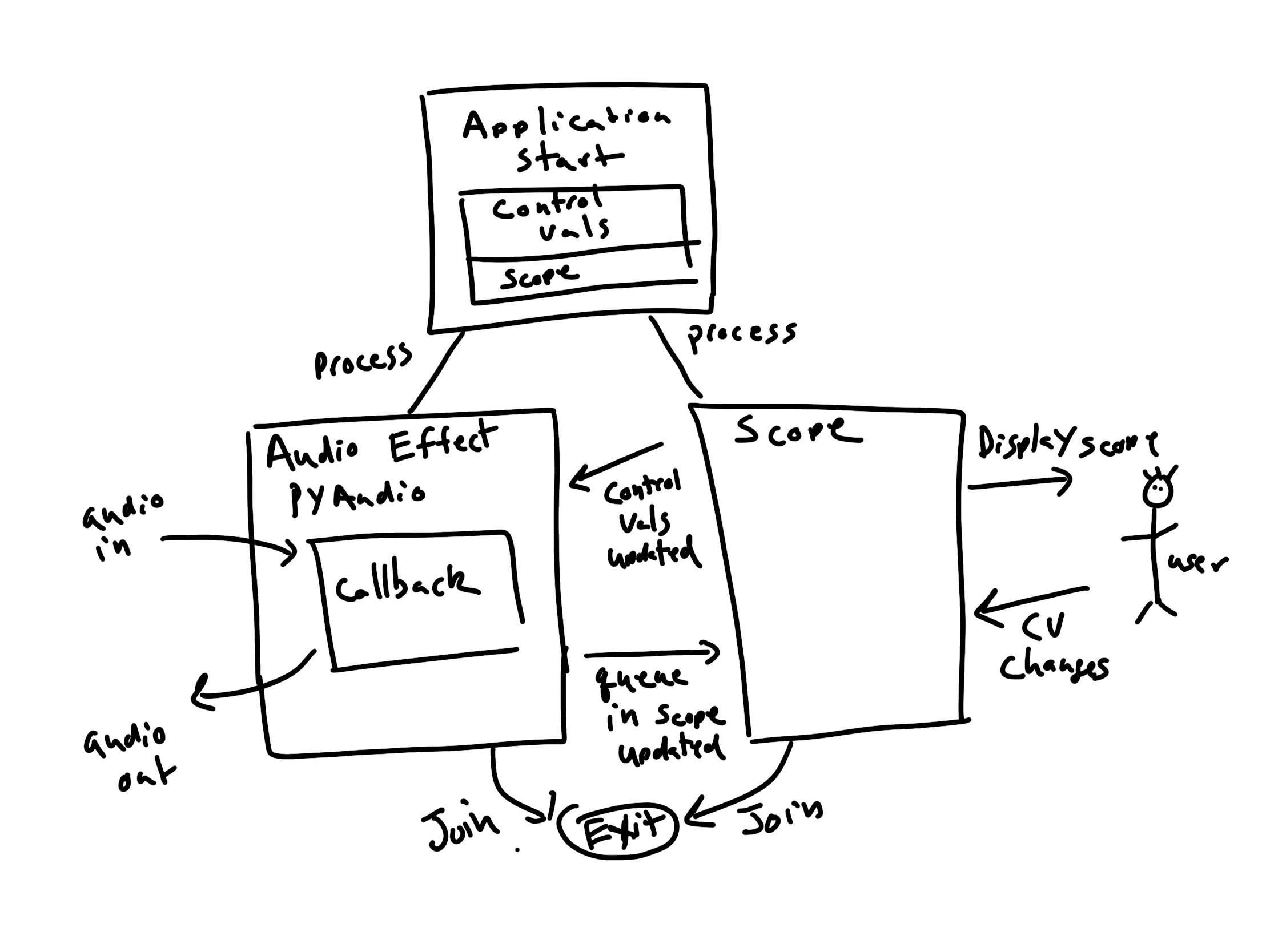
I built a simple (and somewhat hacky) visualizer that uses matplotlib and some of its interactive UI elements (Sliders and CheckButtons) to plot a circular buffer of data coming over a queue from the main PyAudio thread and updating control variables such as Q, sensitivity and the gains. This ended up working way better than I initially expected, and essentially allowed me to play with the audio and parameters live and observe the signals I was working with in real time.
The ControlValues class creates a container for holding the multiprocess value contexts and simplifies access to them, as well as, control access using Locks. The basic
The basic application architecture is:
OBS Studio and obs-websocket
I am going to write a separate blog post on this, but to simplify making the videos for this project I used OBS Studio, obs-websocket, and simpleobsws. OBS Studio sets up a recording, and the websocket allows me to trigger a new recording using the python application. This allowed me to script making all of the videos in this blog post.
Other Resources
- This writeup from Hoch Strasser Electronics is great and I only found it after implementing my own version of the Autowah.